Recently, I have been interested in seeing how the Logitech Harmony 650 remote looks like from a hardware standpoint, primarily since the software to program the devices is absolutely horrible to work with. My primary gripe with it is that its a wrapper around a webpage and very difficult to do certain tasks and has very specific opinions on how your entertainment center is setup. There has been some work in a project called concordance, but I’m not sure that it will fit my needs and still relies on interacting with the logitech site to get codes for the remote and basically just acts like a command line interface for pushing configs to the remote.
Since I had an issue where I needed to disassemble a remote because someone spilt coffee on it, I took the remote apart to clean it and figured would take a look at the guts of it to see the feasibility of modding or changing the firmware.
Software Overview
The software from logitech basically creates a webpage in an app and interacts with the remote via a usb HID. My understanding is that they are basically programming the remote via HID input, so it could be fairly straightforward to reprogram the device via an alternative method. Since it uses HID, it is also likely that it can easily be interacted with via a chrome app, which would be very easy to develop an alternative way of programming it. We also know that the firmware can be updated via the app, so I would suspect that the MCU only has a bootloader and the firmware is stored on the flash memory module.
Hardware First thoughts
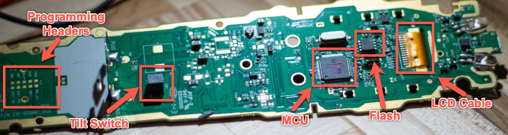
When looking at the board for the first time, there are a couple things that become very obvious and I will point them out for folks who don’t ofent pull hardware out.
- There are readily accessible programming headers, which are likely used by the factory to program the PIC18 MCU
- There is a tilt switch, which is how the LCD knows to turn on/exit power saving mode.
- There is an flash memory chip on the board (we will go into this a bit more shortly)
- LCD is connected via a ribbon cable from the other side of the board.
MCU and Flash Overview
The MCU is a Microchip PIC18F67J50, which is a fairly inexpensive microcontroller with built in USB. The Flash memory is a Macronix MX25L1606E, a 16 megabit (2MB) flash controller.
Onto the Flash contents
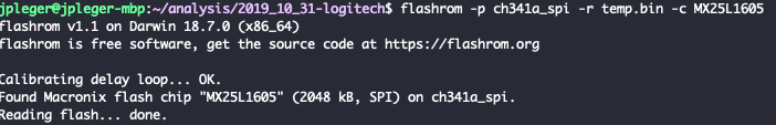
Using flashrom, I was able to dump the contents of the flash memory using a CH341a and a set of SOIC clips without issue.
$ flashrom -p ch341a_spi -r temp.bin -c MX25L1605
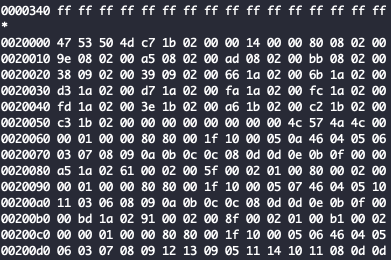
Looking at the dumped file, there are a couple interesting offsets, the first of which is likely the firmware. And later on there are what appears to be some sort of configuration structure.
Moving forward
Now that I have looked at the hardware and have gotten a good idea of how the device is generally setup, I am going to spend a bit of time going through the different HID commands. I will likely take a look at concordance and see what all has been done so I don’t recreate the wheel. Once I have a good idea on what all is possible with the stock firmware, I will see about putting together a chrome app that interacts with the remote.
So the next steps are:
- Determine what the HID codes are so I can interact with the remote
- POC interaction with the remote in Python or Chrome app
- See if there are any debugging methods without using the pins (ideally via USB)
Stretch goals:
- Test debugging ports on remote
- Extract PIC firmware